Gear panel tutorial, part 1 – Three Greens
As an introduction to designing and building custom X-Plane hardware, I’m writing a series on building a typical landing gear panel.
Part 1 – Three Greens

In this article we’ll link three green LEDs to the landing gear position.
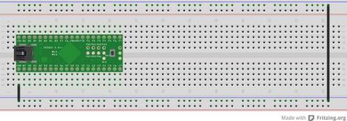
Let’s start with a bare breadboard. Put a Teensy on it and link up the ground rails.

Then, open the Arduino IDE and load the blinkTransponder example. Compile it and upload it to the Teensy. Launch X-Plane and see the little blinking light. By doing this, we achieve two things: we now know that the Teensy is working and we can upload stuff to it OK, and we’ve replaced any previous sketch with one that’s not doing anything unexpected to any of the pins.
Now let’s add some LEDs. Disconnect the cable first! Each LED connects a pin to the ground, in series with a resistor. I use 220-Ohm resistors, because that’s what the Teensy tutorial uses. It doesn’t particularly matter which pins you use. Some of the pins can act as interrupts, PWM outputs or analogue inputs, but they all can act as digital input/output too. Just avoid the Ground, +5V, and Ref pins.

That’s the hardware sorted. Now we can write some code.
It’s always a very good idea to begin by writing code to test your hardware. We’ll adapt BlinkTransponder to blink the three new LEDs as well as the on-board one. If you’ve followed my guide to setting up a Teensy development environment, copy BlinkTransponder into your Qt Creator sketchpad project. If not, just use the Arduino IDE. It’s not that bad.
// Our LED pin numbers
const int greenLeftPin = 10;
const int greenNosePin = 11;
const int greenRightPin = 12;

// Special variable to access the transponder light
FlightSimInteger transponderLight;

// setup runs once
void setup() {
  // set pin mode to output
  pinMode(greenLeftPin, OUTPUT);
  pinMode(greenNosePin, OUTPUT);
  pinMode(greenRightPin, OUTPUT);

  transponderLight = XPlaneRef("sim/cockpit/radios/transponder_light");
  transponderLight.onChange(updateLED);
  pinMode(LED_BUILTIN, OUTPUT);  // pin 11 on Teensy 2.0, pin 6 on Teensy++ 2.0
}

// loop runs repetitively, as long as power is on
void loop() {
  FlightSim.update(); // causes X-Plane's changes to be received
}

// updateLED runs only when X-Plane changes transponderLight
void updateLED(long value) {
  if (value == 0) { // transponder light is off
    // make all the LEDs go off
    digitalWrite(greenLeftPin, LOW);
    digitalWrite(greenNosePin, LOW);
    digitalWrite(greenRightPin, LOW);
    digitalWrite(LED_BUILTIN, LOW);
  } else { // the transponder light must be on
    // make all the LEDs go on
    digitalWrite(greenLeftPin, HIGH);
    digitalWrite(greenNosePin, HIGH);
    digitalWrite(greenRightPin, HIGH);
    digitalWrite(LED_BUILTIN, HIGH);
  }
}
You should be rewarded with the sight of four LEDs blinking erratically in unison if you’ve prudently left X-Plane running while you do this.
Now we need to connect these LEDs to something more useful than the transponder light. Ideally, there would be a set of ‘gear down and locked indicator’ datarefs for each leg of the undercarriage, but as far as I can tell there isn’t. We will have to make our own simulation of the landing gear annunciator logic.
X-Plane uses datarefs to send data from the simulator to the outside world. In the BlinkTransponder example, sim/cockpit/radios/transponder_light is a dataref which indicates the state of the transponder interrogation light. In reality, it flashes up whenever ATC radar detects the aircraft. In X-Plane 9, it just flashes randomly all the time, which looks a bit odd when you’re in the middle of the ocean. We’ll need to find datarefs that relate to the landing gear position.
The best way to investigate datarefs is to use DataRefEditor, or DRE. When you load it, the screen fills with green text describing thousands of datarefs.

There’s an excellent text search feature in the bottom left of the DRE window. When text is entered, it only shows datarefs which have names containing the text you enter. (Press Enter to take focus off the search box and give keyboard input to the rest of X-Plane again.) Searching by the word ‘gear’ I found a promising candidate: sim/flightmodel2/gear/deploy_ratio.

sim/flightmodel2/gear/deploy_ratio=[0/10]:1.000000
We can get a wealth of information from this single line.
sim/flightmodel2/gear/deploy_ratio is the name of the dataref. The flightmodel2 part means this data is coming from the flight model, so it’s pretty much guaranteed to be accurate. Some datarefs, for instance some cockpit indicator datarefs, have instrument failure states modelled. If you take your altitude from the cockpit altimeter dataref, you’ll get inaccurate values if the altimeter fails. Whether this is desirable or not depends on the context!
[0/10] shows two things. This is an array of ten datarefs, and we are looking at the first one. The counting starts from zero. With the right-hand horizontal slider we can select different elements in the array. Each element represents one landing gear leg. Unfortunately there’s no convenient way to discover which element is which leg.
1.000000 is the value of the selected index of the dataref. Because there is a decimal point, we know this is a floating-point dataref, rather than an integer. If we click on the 1.000000, we can try to edit the value. In this case, it doesn’t change – sim/flightmodel2/gear/deploy_ratio is read-only.
Finally, we can test with a short flight that a value of 1.0 means the gear is extended, and 0.0 means the gear is retracted.
Let’s link our new LEDs to this dataref. We’ll link all three LEDS to the first element for now. And I’ll remove the transponder light – that constant flashing is getting on my nerves.
const int greenLeftPin = 10;
const int greenNosePin = 11;
const int greenRightPin = 12;

// Landing gear position dataref
FlightSimFloat gearDeploy0;

void setup() {
  pinMode(greenLeftPin, OUTPUT);
  pinMode(greenNosePin, OUTPUT);
  pinMode(greenRightPin, OUTPUT);

  // assign gearPos0 to first element of gear position dataref
  gearDeploy0 = XPlaneRef("sim/flightmodel2/gear/deploy_ratio[0]");
  gearDeploy0.onChange(updateLED);
}

void loop() {
  FlightSim.update();
}

void updateLED(float value) {
  if (value == 1.0) {
    // make all the green LEDs go on
    digitalWrite(greenLeftPin, HIGH);
    digitalWrite(greenNosePin, HIGH);
    digitalWrite(greenRightPin, HIGH);
  } else {
    // make all the green LEDs go off
    digitalWrite(greenLeftPin, LOW);
    digitalWrite(greenNosePin, LOW);
    digitalWrite(greenRightPin, LOW);
  }
}
A couple of minor points to compare with BlinkTransponder. We’re using FlightSimFloat, not FlightSimInteger, because we’re dealing with a float dataref instead of an integer dataref. This also means that we pass a float to updateLED instead of an integer. Also notice the syntax in XPlaneRef to select an element of an array dataref.
Well that works! All the lights go on when the wheel’s down, and they all go off when the wheels are not down. But what happens when the undercarriage has partly failed? We need to identify which undercarriage leg goes with each index of gear/deploy_ratio.
A little bit of experimentation with the equipment failures screen produces the answer:


deploy_ratio[0] is the nosegear, [1] is the left gear, and [2] is the right gear. For the default King Air at least.
Let’s cut down our code to change the nose-gear light only.
const int greenLeftPin = 10;
const int greenNosePin = 11;
const int greenRightPin = 12;

// Landing gear position dataref
FlightSimFloat gearDeployNose; // we know what the '0' means now.

void setup() {
  pinMode(greenLeftPin, OUTPUT);
  pinMode(greenNosePin, OUTPUT);
  pinMode(greenRightPin, OUTPUT);

  gearDeployNose = XPlaneRef("sim/flightmodel2/gear/deploy_ratio[0]");
  gearDeployNose.onChange(updateNoseGearDeploy);
}

void loop() {
  FlightSim.update();
}

void updateNoseGearDeploy(float pos) {
  digitalWrite(greenNosePin, (pos == 1.0));
}
Look at the digitalWrite statement. Instead of giving it either HIGH or LOW, which are equivalent to true and false, we can put this expression (pos == 1.0) in there instead. When the code is run, it will be evaluated as either true or false.
Let’s extend this code to use all three gear position datarefs:
const int greenLeftPin = 10;
const int greenNosePin = 11;
const int greenRightPin = 12;

// Landing gear position datarefs
FlightSimFloat gearDeployLeft;
FlightSimFloat gearDeployNose;
FlightSimFloat gearDeployRight;

void setup() {
  pinMode(greenLeftPin, OUTPUT);
  pinMode(greenNosePin, OUTPUT);
  pinMode(greenRightPin, OUTPUT);

  gearDeployLeft = XPlaneRef("sim/flightmodel2/gear/deploy_ratio[1]");
  gearDeployLeft.onChange(updateGearDeployLeft);
  gearDeployNose = XPlaneRef("sim/flightmodel2/gear/deploy_ratio[0]");
  gearDeployNose.onChange(updateGearDeployNose);
  gearDeployRight = XPlaneRef("sim/flightmodel2/gear/deploy_ratio[2]");
  gearDeployRight.onChange(updateGearDeployRight);
}

void loop() {
  FlightSim.update();
}

void updateGearDeployLeft(float pos) {
  digitalWrite(greenLeftPin, (pos == 1.0));
}
void updateGearDeployNose(float pos) {
  digitalWrite(greenNosePin, (pos == 1.0));
}
void updateGearDeployRight(float pos) {
  digitalWrite(greenRightPin, (pos == 1.0));
}
There we go – working gear-down-and-locked lights!
Next time, we’ll add the red gear-out-of-position lights.
Awesome article.
How can I get this X-Plane library to work for a regular Arduino Uno? I don’t even see where I can download the library. Is it only included in the Teensyduino installer?
Sorry Jeffrey, these libraries are for Teensy boards only – they don’t work with regular Arduino. (Teensy has a different and better integrated USB controller or some such thing. I don’t understand it.)
People have successfully used natural Arduinos to make custom hardware, writing their own code to communicate through the USB serial port, but I don’t know much about this – the only electronics boards I’ve used are Teensy, and only after Paul made the X-Plane library to abstract that serial port away.
I couldn’t find the blink transponder example anywhere….. Could u pls post it somewhere that I can copy it and upload to my Teensy
Rgds
Alex
Hi Alex,
In the Arduino editor (after installing TeensyDuino), go to File menu >> Examples >> Teensy >> USB_FlightSim >> BlinkTransponder.
Then in the “Tools” menu, set “Board” to whichever Teensy you’re using, and “USB Type” to “Flight Sim Controls”. And then, you should be able to compile and upload!
Current software versions are Arduino editor v1.0.5, and TeensyDuino v1.17.
Started working when I found out about the reqd plugin! Thx!
Wanted to say that this was very east to follow. Great instructions, Only took about an hour from start to finish. Do you have any other examples for getting some of the other LED’s to light up in the 737. THANKS AGAIN!!!